1. The eight core processes
| Process | What it does |
|---|---|
| Photolithography | Transfers circuit patterns onto the wafer by shining light through a mask onto a light-sensitive photoresist. |
| Etch | Removes material exposed during lithography, using plasma (dry) or chemicals (wet), to carve circuit features. |
| CVD | Chemical vapor deposition grows high-purity dielectric or insulating films through gas-phase reactions. |
| Metal | Deposits thin conductive layers and fills vias to wire components together. |
| Diffusion | Heats wafers in a furnace to grow precise oxides or drive dopants deeper into the silicon. |
| Implant | Fires high-energy ions into the substrate to change its conductivity, forming n-type or p-type regions. |
| CMP | Chemical mechanical planarization flattens each layer with slurry and polishing before the next one. |
| Clean | Removes particles, metal residue, and chemical contamination between steps to protect yield. |
Electrical die sorting (EDS) and packaging complete the flow.
2. Front end and back end
Front end - FEOL (front-end-of-line): builds the source, drain, and gate. - MOL (middle-of-line): makes the conductive plugs that link transistor contacts to the metal wiring above, connecting FEOL and BEOL. - BEOL (back-end-of-line): builds the metal interconnects.
Back end - Advanced packaging: connects multiple chiplets into a single package.
3. Wafer production
Czochralski (CZ) method
Makes wafers up to 300 mm (12 in). Used for CPUs, GPUs, and memory.
- Melt the silicon in a quartz crucible. Si melts at 1420 °C, and dopants can be added to the melt.
- Insert the seed. A perfect single-crystal seed on a rod touches the melt. Liquid Si adheres and aligns to the seed's orientation, usually ⟨100⟩ or ⟨111⟩.
- Necking. The seed is first pulled up quickly while rotating (opposite to the melt). This drives dislocations out to the surface, leaving defect-free crystal below.
- Shoulder and body growth. The pull slows to reach the target diameter.
- Tail-off and cooling. Near the target length, pull speed and temperature rise to taper the end into a cone, preventing thermal stress from cracking the crystal as it leaves the melt.
Float-zone (FZ) method
Makes ultra-pure single-crystal silicon but is hard to scale to large diameters. Mainly used for power devices.
- A high-purity polysilicon rod is mounted vertically in a sealed chamber.
- A single-crystal seed touches the bottom of the rod.
- An RF induction coil around the rod melts a narrow band where the seed meets it.
- The coil moves slowly upward. Molten Si recrystallizes behind it, following the seed's lattice.
- Dopant gases can be introduced as the zone moves, followed by cooling.
From ingot to wafer
- Crystal growth
- Single-crystal ingot
- Diameter grind
- Flat grind
- Slicing
- Edge rounding
- Lapping
- Wafer etch
- Polishing
- Inspection
- Edge rounding: a rotating milling cutter rounds the wafer edge, improving thermal resistance.
- Lapping: grinds the backside to reduce thickness and stress.
- Wafer etching: wet etching (NH₄OH, CH₃COOH, HNO₃) removes defects from earlier steps.
- Polishing: two or three passes with slurry smooth the surface.
4. Equipment
Chamber
- A closed space for controlling pressure, heat, and gas.
- Research tools usually have one chamber.
- Industry uses cluster tools: a central transfer chamber surrounded by several process chambers.
- Wafers go in through a load lock, move to the transfer module, then to a process chamber.
- Chambers can share settings or each run a different process.
- Cluster tools are common for deposition (CVD, PVD, ALD) and dry etch.
Chuck
Holds the wafer in the chamber. - Vacuum chuck: suction holds the wafer down. Works only at atmospheric pressure. - Electrostatic chuck: high voltage in a ceramic chuck attracts the wafer. Works in high vacuum and can control wafer temperature with helium flow or heating and cooling beneath the wafer.
Mass flow controller (MFC)
Measures and regulates gas flow into the chamber. - Measures flow by mass (number of molecules) rather than volume. - A heating coil and temperature sensors heat the gas and sense the temperature change. More gas flow means a smaller fluctuation, less flow a larger one. - Valves open and close to control the flow.
Scrubber
Neutralizes hazardous exhaust before it reaches the atmosphere. - Burn (thermal) scrubber: flames or plasma decompose stable or harmful greenhouse gases. - Wet scrubber: water or chemical sprays dissolve acid gases. - Dry scrubber: solid absorbents capture toxic gases at room temperature.
Gases then go to the fab's central scrubber system for final treatment.
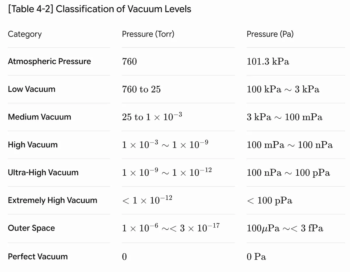
5. Vacuum
Ideal gas law
PV = nRT
P is pressure, V volume, n moles, R the gas constant, and T temperature. Vacuum pressure is proportional to the number of moles, so lowering pressure means pumping molecules out. The ideal gas law applies well because so few molecules remain.
- Boyle's law: at constant temperature, pressure and volume are inversely proportional.
- Charles's law: at constant pressure, volume and temperature are directly proportional.
- Avogadro's law: at constant volume and temperature, pressure is directly proportional to the number of moles.
Properties of gases
- Molecules move rapidly in random directions and are separated by large distances.
- They have no attractive or repulsive forces between them.
- Collisions are perfectly elastic, with no kinetic energy gained or lost.
- Average kinetic energy is directly proportional to absolute temperature.
Mean free path (MFP)
The average distance a molecule travels before hitting another. Higher pressure means more molecules and a shorter MFP.
λ (cm) ≈ 0.7 / P (Pa) ≈ 5 × 10⁻³ / P (Torr)
Monolayer formation time (MFT)
The time for gas to cover a clean wafer with one atomic layer. A shorter MFT means a faster process. Higher pressure means more molecules hitting the wafer, so a shorter MFT.
τ (s) ≈ 3 × 10⁻⁴ / P (Pa)
Molecular velocity
The average speed of gas molecules. Since kinetic energy is proportional to absolute temperature, lighter molecules move faster than heavier ones at the same temperature.
Vacuum system
Deposition and etching normally happen in a vacuum chamber.
| Component | Role |
|---|---|
| Vacuum chamber | The space where vacuum is created. |
| Vacuum pump | Evacuates gas from the chamber. |
| Vacuum gauge | Measures the vacuum level. |
| Vacuum valve | Connects the chamber to external systems. |
| Sealing | O-rings and gaskets keep outside gas out at connections. |
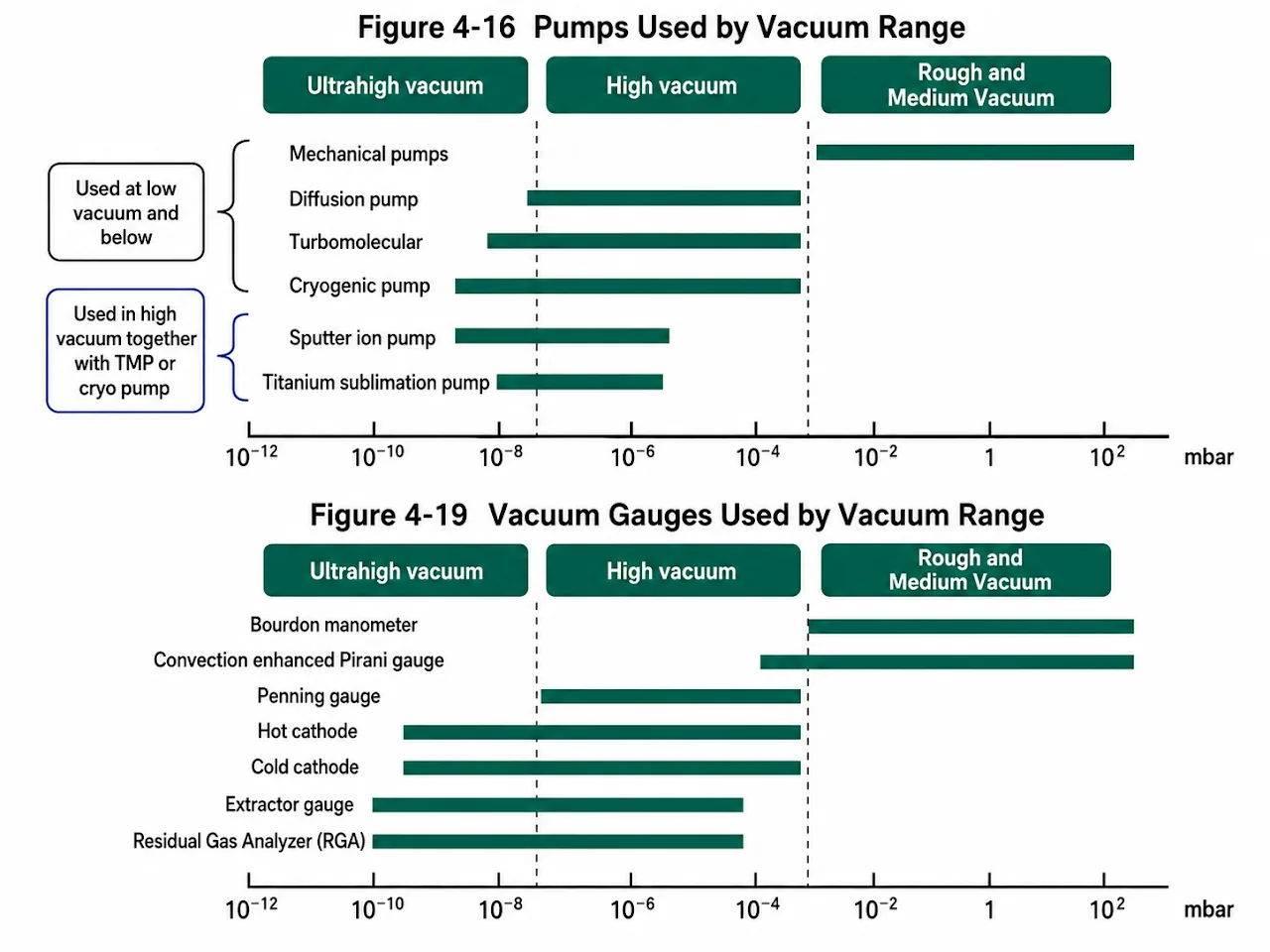
Vacuum pumps
Low vacuum (to about 10⁻¹ Torr) - Rotary pump (oil-filled): rotor turns → gas is isolated → compressed → exhausted. - Roots pump (common in production): same mechanism. It's paired with a rotary pump, with the Roots upstream pulling large gas volumes and the rotary downstream handling back-pressure and venting.
High vacuum (to about 10⁻⁷ Torr) - Turbomolecular pump: stacks of blades spin at 60,000–100,000 rpm. It needs a backing pump for its exhaust, and must run at low pressure because gas friction at atmosphere would destroy the thin blades. - Cryopump: liquid He cools internal plates below 15 K. Gas freezes onto the plates (condensation) and is trapped (adsorption). Trapped gas must be cleared periodically (regeneration), so it runs at low pressure to avoid frequent regeneration.
From low to high vacuum 1. Open valve A between the chamber and the low-vacuum pump. 2. At low vacuum, close A, open valve B (chamber to high-vacuum pump) and valve C (high-vacuum pump to low-vacuum pump). 3. Gas from the high-vacuum pump passes to the low-vacuum pump and is exhausted. 4. Both pumps run continuously, and the vacuum level is controlled with the valves.
Vacuum gauges
- Capacitance manometer: a flexible metal diaphragm separates the chamber from a reference vacuum. As pressure changes, the diaphragm bends and changes the capacitance. Used for accurate process-pressure control.
- Pirani gauge: a heated filament is exposed to the gas. At high pressure more molecules carry heat away and cool it. The gauge reads the filament's temperature-dependent resistance. Used for low to medium vacuum.
- Ion gauge: electrons ionize gas molecules, and collector plates read the resulting current. More current means higher pressure. Used for high and ultra-high vacuum down to 10⁻¹⁰ Torr.
Pump efficiency
- Higher pumping speed and pipe conductance improve efficiency.
- Connections must seal well: O-rings below 150 °C, copper gaskets above.
1 / Seff = 1 / C + 1 / Spump
Seff is the effective pumping speed, Spump the pump's speed, and C the conductance.
6. Plasma
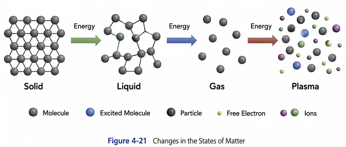
What plasma is
- Often called the fourth state of matter.
- An ionized gas formed by applying strong electrical or RF power to gas in a vacuum chamber.
Glow discharge
The soft glow emitted when low-pressure gas is ionized by an electric field. - Free electrons accelerated by the field hit neutral atoms. Cosmic rays, background radiation, and photoionization always leave a few stray seed electrons in the chamber. - Atoms absorb the energy and their electrons jump to higher levels. - When they fall back, they emit the extra energy as visible light.
Quasi-neutrality
- Overall, plasma stays electrically neutral: positive ion and electron densities almost exactly balance.
- Plasma also shows collective behavior in an electric field.
How plasma forms
- Ionization. Power accelerates free electrons, which knock bound electrons out of neutral atoms (e⁻ + A → A⁺ + 2e⁻). This avalanche turns inert gas into a conducting plasma.
- Dissociation. Electrons break the bonds of molecular gases without necessarily ionizing them (e⁻ + AB → e⁻ + A + B). The fragments are highly reactive neutral radicals that do chemical etching or deposition.
- Excitation. Lower-energy collisions lift a bound electron to an excited state (e⁻ + A → A* + e⁻).
- Relaxation. Within nanoseconds the excited electron drops back and emits a photon (A* → A + hν). Optical emission spectroscopy reads these wavelengths to track chamber chemistry in real time.
- Recombination. Positive ions meet electrons, and radicals meet each other or the walls, cancelling charge or re-forming stable molecules.
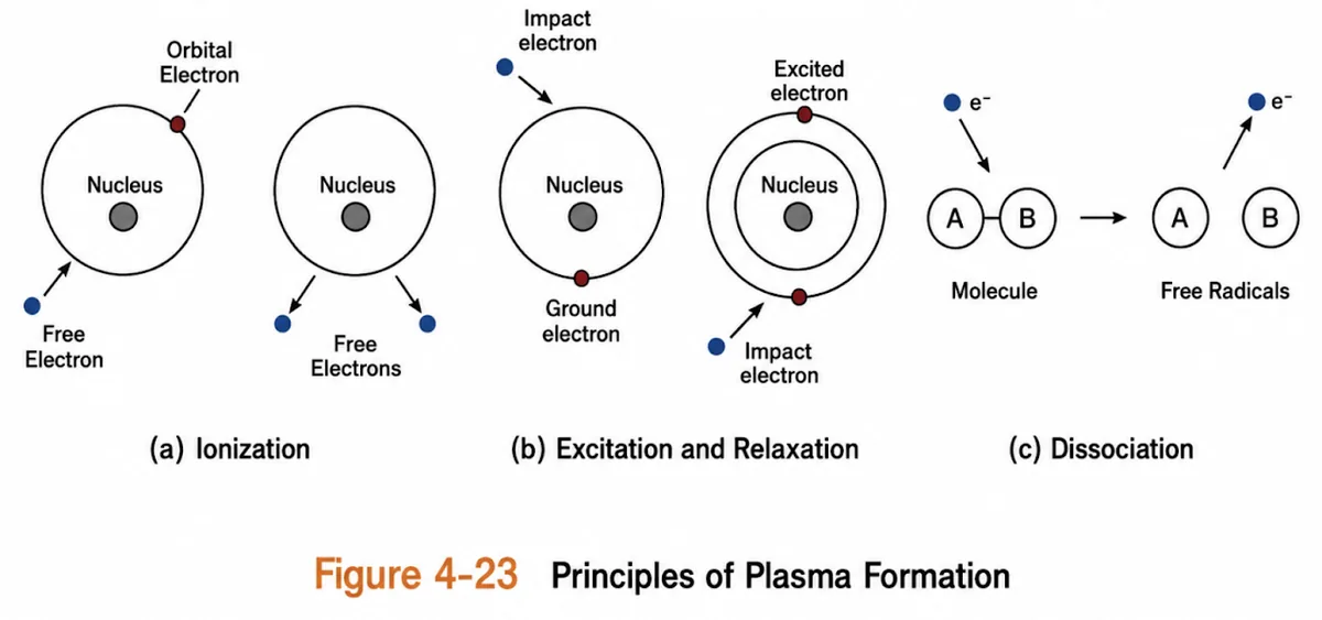
Ions and radicals are both used in processing: - Ions drive PVD, especially sputtering. - Radicals drive PECVD. - Ions plus radicals drive reactive ion etching (RIE).
All five steps happen at once because electrons have a spread of energies (a Maxwell distribution): - The highest-energy electrons ionize, medium-energy ones dissociate and excite, and low-energy ones recombine. - While RF is on, new ions and radicals form as fast as old ones are neutralized, so the plasma glows steadily. - When RF turns off, ionization, dissociation, and excitation stop immediately, and recombination and relaxation take over for a fraction of a second.
Plasma characteristics
Here "plasma" means the glow-discharge plasma used in manufacturing. By energy source it can be DC, RF, or microwave plasma.
- Plasma is generated with voltage rather than heat because voltage is easier to control.
- Electrons accelerated by the field ionize neutral atoms and molecules.
- At the boundary, electrons and ions are lost when they hit walls or electrodes and are neutralized.
- Ionization replaces them, keeping a dynamic equilibrium: ions created equals ions lost.
- Electrons are much lighter than ions and move faster, so they reach the walls first, building a negative charge. That charge repels further electrons and attracts slower positive ions. This self-balancing zone is the plasma sheath.
Plasma sheath (Debye sheath)
A thin boundary layer that forms wherever plasma meets a surface (walls, stage, or wafer). It's what makes directional etching possible.
Formation - Bulk plasma is quasi-neutral (nᵢ = nₑ). - At ignition, the faster electrons reach the surfaces first and charge them negatively.
Self-balancing - The negative surface repels electrons, so only the most energetic get through, and it attracts positive ions. - Equilibrium is reached when the incoming electron and ion rates match.
The sheath zone - A narrow region next to the wall where electrons are repelled and positive ions dominate (nᵢ ≫ nₑ), so it isn't neutral.
Why it matters - Anisotropic etching: the sheath field points straight at the wafer, so ions entering from the bulk plasma accelerate down in straight lines. - Dark space: with almost no free electrons in the sheath, there's no excitation and no glow, leaving a dark gap above the wafer and walls.
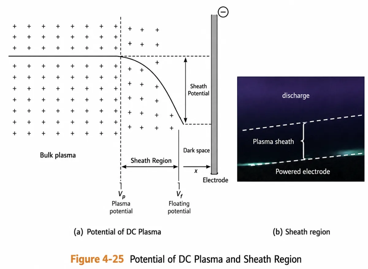
- Plasma potential (Vp): the potential inside the nearly neutral bulk plasma.
- Floating potential (Vf): the potential an electrically isolated object reaches in the plasma.
- Sheath potential: the voltage drop across the sheath, between bulk plasma and a wall or electrode.
Generating plasma
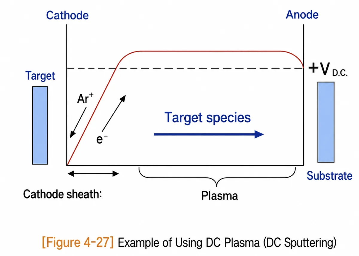
DC plasma - A DC voltage across two parallel plates: the anode is grounded and the cathode is held at −200 to −1000 V. Electrons move opposite to the field. - Free electrons ionize neutral atoms. Positive ions slam into the cathode and release secondary electrons in about 10% of impacts. - Secondary electrons accelerate toward the anode, ionizing more molecules, so ionization snowballs. - Equilibrium is reached when new ion–electron pairs balance losses at the electrodes. When the voltage turns off, the plasma goes out.
Sputtering (DC-plasma PVD) - Uses inert Ar to avoid chemical reactions. - Ar⁺ ions accelerate to the negative cathode (the target) and knock material loose. - The sputtered material travels to the anode side and deposits on the substrate.
RF plasma - The field alternates at 13.56 MHz. Light electrons follow it, while heavy ions barely move. - Electrons oscillating between the electrodes collide with more gas molecules, making the plasma more efficient. - RF can etch and deposit insulators. With DC, positive charge builds up on an insulating surface, blocks the field, and kills the plasma. With RF, each polarity flip sends a wave of electrons that neutralizes that charge. - Self-bias (Vdc): fast electrons hit the powered electrode far more often than ions, so a negative DC voltage builds on the wafer electrode, enabling directional etching. Two things make this happen: - A blocking capacitor between the RF generator and wafer electrode passes RF but blocks DC from flowing back. - Asymmetric electrodes: the powered electrode holding the wafer is much smaller than the grounded surfaces.
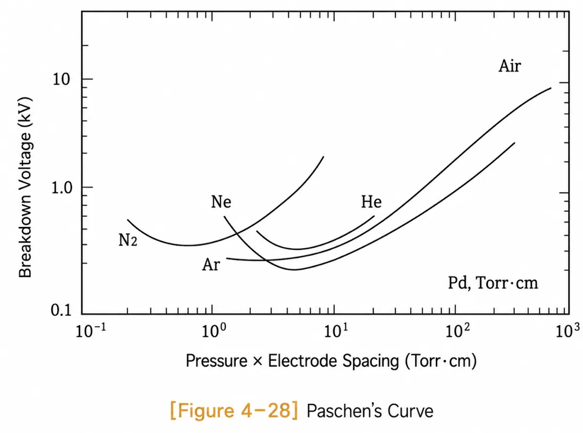
Paschen's curve
- The breakdown voltage needed to ignite a plasma depends on the product of gas pressure and electrode spacing: V = f(P × d).
- The U shape means plasma is hard to ignite at very high or very low P × d, with a sweet spot in between.
- High P × d: the chamber is dense with molecules and the MFP is very short. Requires high voltage.
- Low P × d: molecules are far apart. Also requires high voltage.
- Paschen minimum: the MFP is long enough for electrons to gain ionizing energy, and the gas is still dense enough for frequent collisions. Requires the minimum voltage.
In practice electrode spacing is hard to change, so voltage and pressure are adjusted to tune plasma efficiency.